Inter-sample overs is something of a mis-understood issue that need not be an issue but it depends upon how format conversion interfaces, including but not restricted to digital to analog converters in devices, are designed and implemented. Indeed my old and failing third generation Yamaha CDX750 CD player had absolutely no problem with inter-sample overs, nor does any first generation CD player which had nothing but analog filtering for DAC signal reconstruction. The reason that is the case is because both the full analog reconstruction filter case and the 1 bit 256 times oversampling delta sigma converter in the CDX750 had sufficient headroom to reconstruct the continuous signal without clipping.
Theoretically at least, it is perfectly possible to design an oversampling delta-sigma DAC with sufficient additional headroom for the up-sampling digital filter so that clipping does not occur. What the truth is with regard to actual available converters seems to be mixed, at least as far as my own personal experience is concerned. How have I come to know this? Of late I have had a number of cases of sheer frustration with designing what sounded like fabulous mastering jobs in Har-Bal on my laptop, the sound being generated by the laptop DAC, only to find that on burning the result to CD and playing back through my newer CD player, that it has an element of harshness and distortion that was not apparent when monitoring through Har-Bal and a different DAC. Clearly a case of the dreaded inter-sample over and a not so good DAC design.
Because of my negative and frustrating experiences with this phantom distortion (phantom because it only occurs at the point of reconstruction in inferior devices) I have added an oversampling interpolator to the envelope detector of Har-Bal 3.7 release 2. This article documents its design and actual performance.
The Design
For a limiter to be able to account for inter-sample overs it requires the ability to be able to predict what those inter-sample peaks will be. You might think that to do this perfectly shouldn’t pose a problem but it does. To be able to perfectly account for the potential problem of inter-sample overs requires knowledge of the processing that is going to be performed on the sampled signal that would potentially result in clipping. Why so? Because we can’t reconstruct the whole analog signal as this would require interpolating to an infinitesimal degree, with corresponding enormous computation times. The best we can do is choose what is most commonly going to be experienced down the signal chain. To that end, most current day sigma delta DAC’s on the market these days employ 4 times oversampling so that became my design choice for the interpolator.
However, it is not enough to simply know the level of oversampling that will be used in the up stream processing for perfect avoidance of overs. You must also have the same interpolator filter response as that of the converter to realize the same inter-sample values. If there are differences then the reconstructions in either case will be different and the actions taken, as far as limiting is concerned, will not be the perfect one. However, it probably isn’t as incongruous as I’m making it out to be. All reconstruction filters will typically have a maximally flat brick wall approximation response so the all important impulse response of the reconstruction filters are likely to be a reasonably close tapered approximations to the ideal sync function impulse response of a perfect but unrealisable reconstruction filter. So what to choose for the filter characteristics.
In an earlier attempt to solving this problem about a year ago I used a filter design based on equi-ripple response in frequency domain to obtain the most stop band attenuation for the least number of filter taps (least computation time required) but this has a nasty consequence in that the impulse response of the interpolator is not at all close to the idealised one and doesn’t work well as an interpolator. Realising my mistake, this time around I chose to realise the filter response using the window method combined with a hamming design window function. To design the filter I made use of the signal package in the R computational statistics program freely available from the R foundation (CRAN) website. I find it a very handy program for testing algorithms with and doing general design work prior to implementing real time implementations. Certainly a lot simpler than coding in C or C++ to design and validate with. In this case the code is a mere 5 lines.
require(signal)
# Reconstruction / interpolation filter for 4 times oversampling
f1 <- fir1(76, c(0.22), type="low")
freqz(f1, Fs=2)
plot(f1, type="l")
plot(cumsum(f1), type="l")
The first line simply ensures the signal package is loaded, the call to fir1() designs the filter response and the remaining 3 function calls plot the design frequency responses, the impulse response and the step response respectively. The frequency responses are shown below.
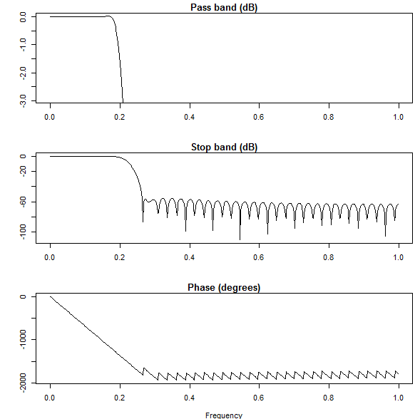
Interpolator Design Frequency Response.
There is a compromise to be made as to how accurate the response is (narrowness of transition band and the level of attenuation in the stop band) and how computationally easy it is to implement. The more accurate response demanded the more computational load required. My gut feeling on this matter was that 60dB of stop band attenuation should be adequate and a 77 point / tap FIR would be sufficient for the task. Indeed, for the responses shown the stop band is typically more that 60dB and for the worst case sampling regime of 44.1kHz (it is worst because it has the narrowest transition band from 20/44.1 to 22.1/44.1) the reconstruction frequency response is about -3dB down at 18kHz and essentially flat from 10kHz down. Also, the inter-sample disagreement between samples for a DC signal is a mere 0.023dB so that is pretty close to ideal.
Now you might be thinking that having a -3dB point of 18kHz doesn’t sound particularly good but this has no effect on the frequency response of the limiter because the limiter is processing the unadulterated (not up-sampled) signal and the interpolator is only being used to determine the signal envelope. The net effect of this frequency response error is likely to be small on envelope detection owing to the fact that for typical music signals the amount of energy at those frequencies is relatively weak. At most, it may create a minor underestimation of the level of inter-sample peaks. Given that there are other factors that limit the ability to make a perfect limiter this merely adds another bit to the approximation. To avoid overs in the majority of cases we will need to be a little more conservative which we do so by lowering the limiter out-ceiling (the space between the level at which no signal should pass and the maximum possible level 0dB).
The impulse response of the filter design is, as expected, an approximation of the sync function (sin(x)/x), as shown below.
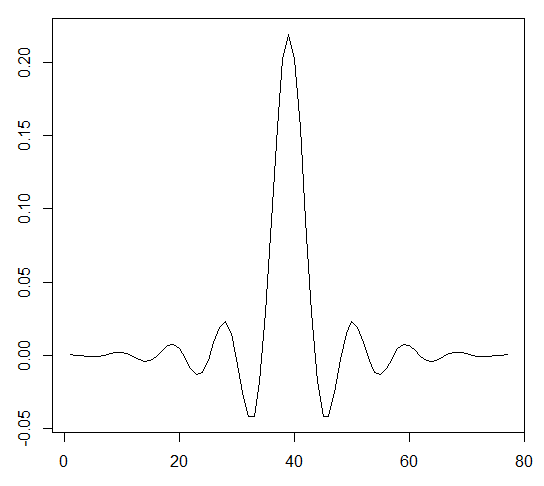
Interpolator Impulse Response
Similarly, the step response of the filter is the familiar looking reconstruction filter response with Gibbs effect ringing often seen in performance plots for DAC’s and other devices.
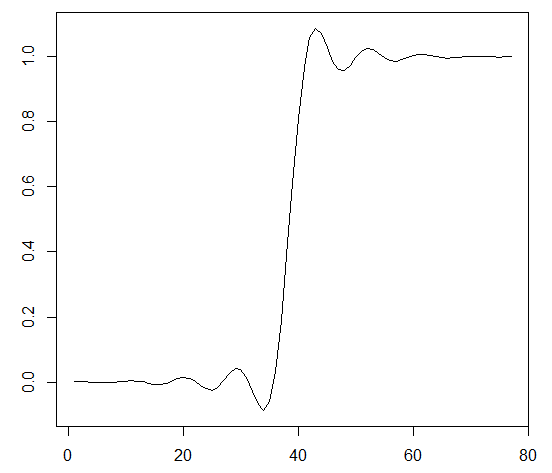
Interpolator Step Response
From the introductory video to Har-Bal 3.7 you will recall that the Har-Bal limiter is in fact three composite limiters. One limiter limiting low frequency content, one limiting the remainder and the final limiter limiting the sum of the previous two limiters. This arrangement minimizes “breathing” (modulation of the sound of one instrument by another most commonly bass instrument – most common cos they carry the most signal power). Naively we might think that we need to incorporate oversampling in all three limiters though in fact we only need it in one, the final stage. This reduces the computational load posed by the interpolator by a factor of three, a substantial saving.
Now let us turn our attention to how well this limiter modification actually performs with real material.
Assessing The Limiter Performance
To assess the performance of inter-sample limiting we need a means of measuring it. The simplest way to achieve this end is to take limited material in digital form, lower its signal level by a sufficient fixed amount (I chose 6dB) and then perform high quality oversampling to up sample the signal to four times the original sampling rate. I used my now aging copy of Adobe Audition for this purpose. The piece of music I chose as source material was something I previously had trouble with in the previous incarnation of the Har-Bal limiter : Foo Fighters – Enough Space.
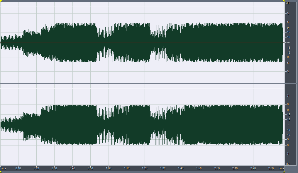
Firstly we can see below the timeline of the original track attenuated by 6dB followed by the 4 times over-sampled result and the corresponding statistics.
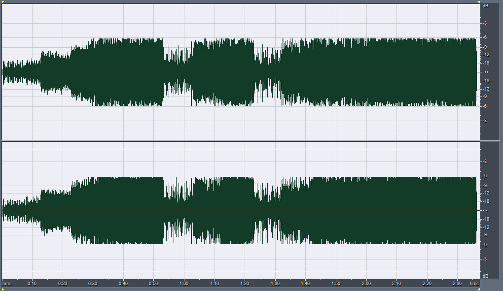
Foo Fighters – Enough Space, attenuated -6dB
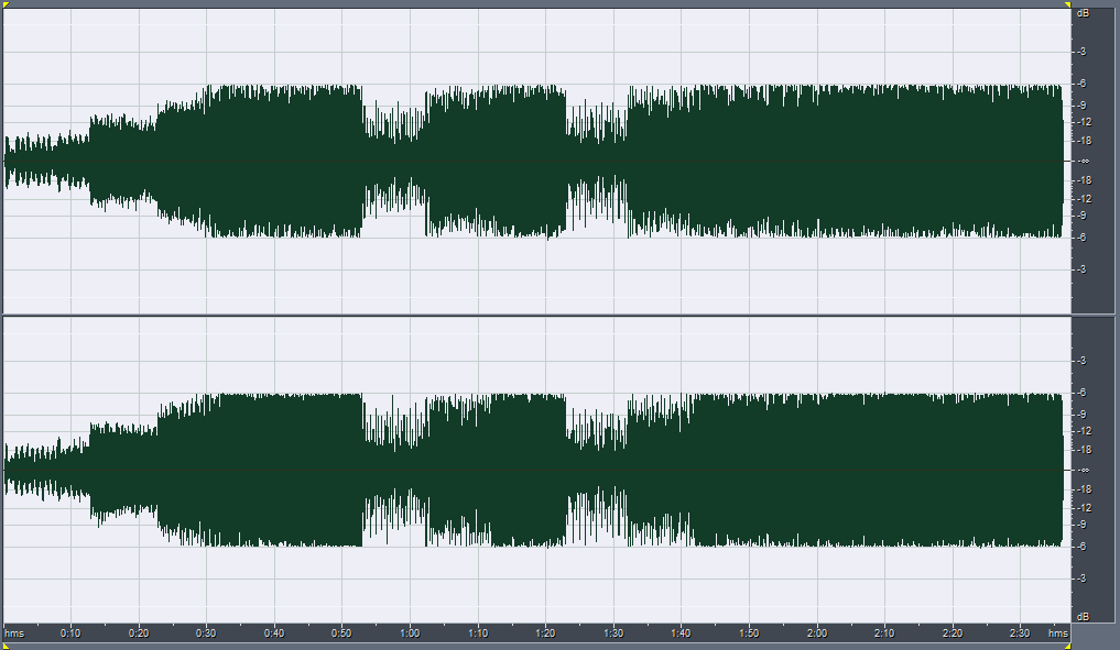
Foo Fighters – Enough Space, attenuated -6dB and 4 times over-sampled
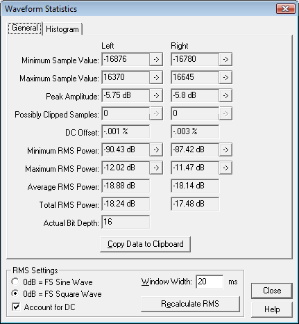
Foo Fighters – Enough Space, attenuated -6dB and 4 times over-sampled : statistics
Although the interpolated results look like they have no digital overs, there in-fact are in this case. This is born out in the the statistics which show maximum levels of -5.75dB and -5.8dB for the left and right channels respectively. This corresponds to overs of 0.25dB and 0.2dB respectively! Probably another reason why I can’t stand listening to that on my CD player. The other part being the track balance which I don’t like at all but that is another story, suffice to say that what follows are timeline results for a re-mastered version of said track in Har-Bal 3.7 release 1 and Har-Bal 3.7 release 2 respectively.
For version 3.7 release 1 we similarly have the same kind of performance graphs.
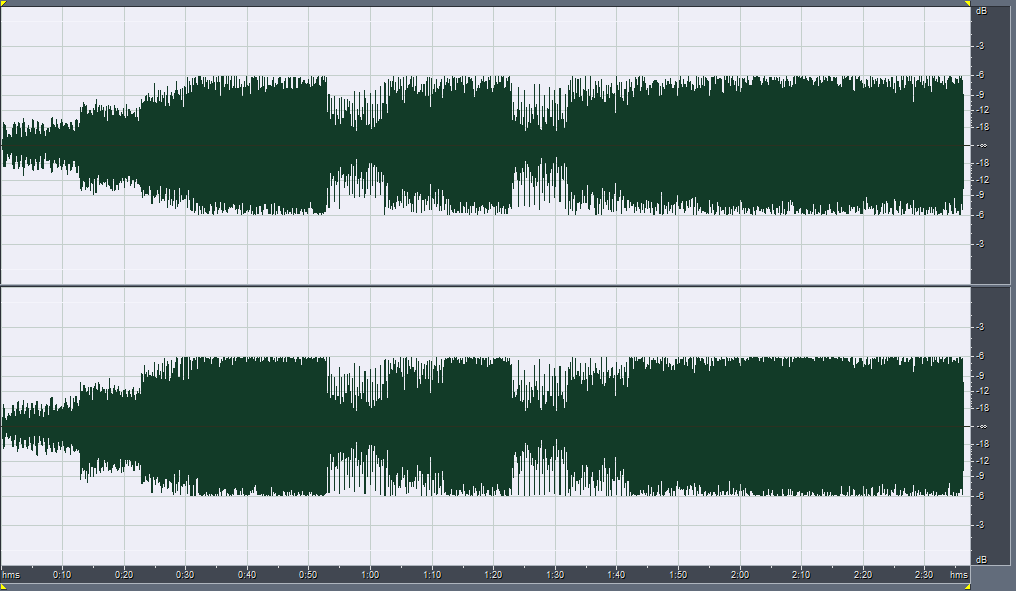
Foo Fighters – Enough Space, Har-Bal 3.7 release 1 re-mastered attenuated -6dB
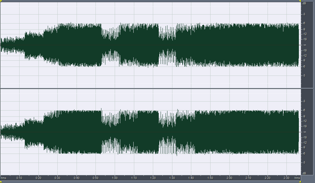
Foo Fighters – Enough Space, Har-Bal 3.7 release 1 re-mastered attenuated -6dB and 4 times over-sampled
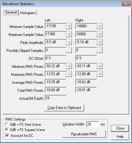
Foo Fighters – Enough Space, Har-Bal 3.7 release 1 re-mastered attenuated -6dB and 4 times over-sampled : statistics
In this case we have peak amplitudes of -5.5dB and -5.16dB for left and right channels respectively corresponding to the considerably worse inter-sample overs of 0.5dB and 0.84dB respectively. Clearly, if my CD player doesn’t handle inter-sample overs properly this would certainly cause the audible distortion I heard after burning my re-master to CD.
Finally, for version 3.7 release 2 we have the following performance figures.
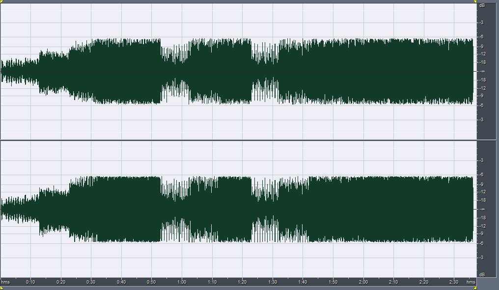
Foo Fighters – Enough Space, Har-Bal 3.7 release 2 re-mastered attenuated -6dB
Foo Fighters – Enough Space, Har-Bal 3.7 release 2 re-mastered attenuated -6dB and 4 times over-sampled
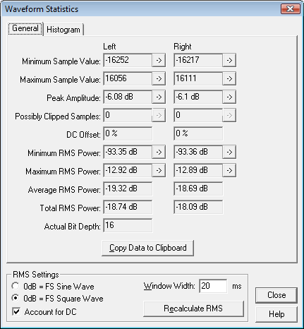
Foo Fighters – Enough Space, Har-Bal 3.7 release 2 re-mastered attenuated -6dB and 4 times over-sampled : statistics
In this case we have peak values of -6.08dB and -6.1dB for the left and right channels respectively giving actual peak levels of -0.08dB and -0.1dB respectively. Close to inter-sample overs / clipping but definitely not! In an attempt to guarantee no overs (due to mismatching between the limiter interpolator and whatever upstream processing to occur that could give rise to overs) I needed to lower the out-ceiling by 0.2dB. Intriguingly, this hasn’t directly translated to average level differences between release 1 and release 2 with release 1 being 0.07dB different rather than a more expected 0.2dB. Perhaps the presence of inter-sample information in the envelope detection has allowed the limiter to perform more effectively, or perhaps it is the dreaded droop in envelope detection frequency response above 10kHz that is the determining factor.
It will take significant further work to get to the bottom of this but on the face of it, the limiter in Har-Bal 3.7 release 2 behaves well for this rather extreme track and shows no inter-sample overs, in contrast to both Har-Bal 3.7 release 1 and whatever limiter was used to master the original Foo Fighters track in question. In defence of the less than admirable performance of release 1, the EQ processing being performed by Har-Bal could be described as quite extreme so that could well bias the results against it, but in any case, the latest release clearly illustrates the effectiveness of the current limiter implementation.
As a final comment on the subject of inter-sample overs and how it is often erroneously referred to as a distortion, clipping or a physical over, this performance evaluation perfectly illustrates why it isn’t. If you took it as gospel that and inter-sample over is clipping then how is it possible to take a clipped track and re-limit it to make it un-clipped (ie. remove the inter-sample over)? That is exactly the scenario here and it is generally true that you can take a track with inter-sample overs and feed it through a limiter capable of limiting to those overs to remove the overs and that supposed distortion. Hence, it technically isn’t a distortion but becomes one in equipment or processes incapable of handling the higher level in-between samples!