Suffice to say that I’ve had enough experience with making speakers in the past to know that it is worth testing a physical realisation of the design first before settling on it. Unforeseen consequences are all to common, even in the case of the extensive modelling that I’ve done.
The biggest question for me in the whole design which isn’t accurately represented in the modelling is the tweeter set-back. The modelling simply assumes that you can realise the time delay required without any impact on the driver frequency responses, which is a quite big assumption. The manufacturer specs assumes the drivers are mounted on a flat baffle. A flat baffle isn’t possible because we need to have the tweeter set back (or the mid-range set forward) by 25.4mm. This necessarily introduces boundaries in the baffle that can reflect sound and alter the driver responses.
My original naive idea was to set back the tweeter in a recess smoothly shaped to try an minimise diffraction effects on the tweeter response. I’m made the prototype shown below to test it as I wasn’t at all confident it would work satisfactorily.
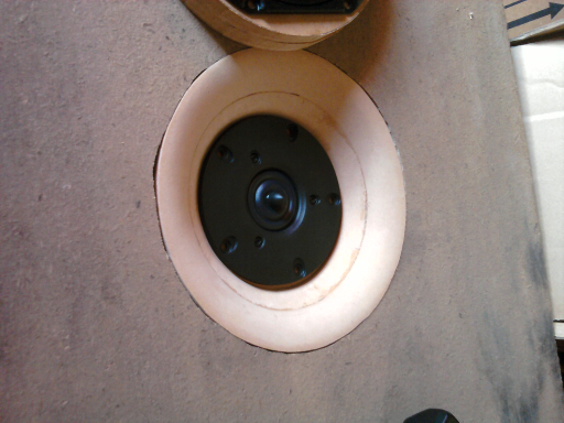
As it turns out my naive idea was a bad idea because it substantially alters the frequency response by focusing sound in the 5khz region forward. This is completely unsatisfactory from my point of view so I had to re-think my approach.
My second line of thinking revolved around the idea of setting the mid-range forward the desired amount and scattering any sound directed at the flange setting the driver forward. Ideally something like a quadratic diffuser would be ideal but the space required for such an approach simply isn’t there. The next best option would be to push the wave front out into space in a direction where it would least effect the driver frequency responses. To that end I ended up with the flange shown below.
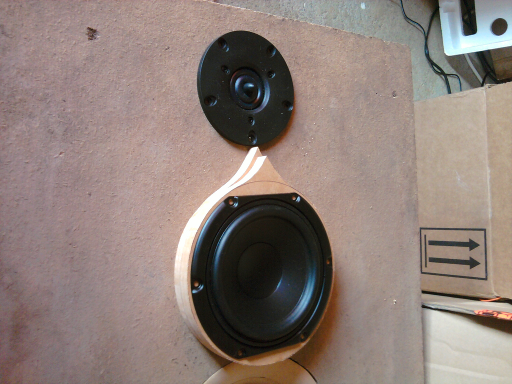
Here I’ve introduced a pointed cusp on the flange to direct incident sound towards the sides and have avoided cutting the flange with a tapper so as to avoid directing reflections forward. Measurement and listen both confirm that this approach has minimal effect on the tweeter driver response so it will be the approach I take in the final design. Knowing the changes required I have to go back and modify my final cabinet design which assumed the former approach.
The crossover board design and construction is a complicated affair. Not wanting to do any circuit board etching I needed to figure out how to lay out the components on a board with copper cuts made to form the tracks, all on a board that is small enough to fit through the hole for the woofer. Given the highly over rated polycarbonate capacitors (400V working) the capacitors are huge and take up quite a bit of real estate as do the inductors. That and having circuit board stock of 305mm square to work from meant that putting the entire crossover on the one board was simply not possible. Instead I made a prototype board that has the mid-range and tweeter parts on a board measuring 305 by 152mm (narrow enough to fit through the woofer port) with little room to spare. The assembled board is shown below,
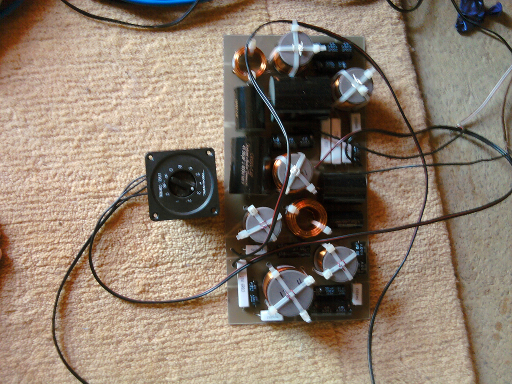
Along with the prototype board you can see an L-Pad that I’ve inserted to figure out the correct tweeter padding needed for a flat on axis response. I don’t know why it is, but every time I’ve attempted to get the padding right from manufacturers specs alone it’s invariably been wrong and this time is no different in that respect. The tweeter needs an additional 3 dB of padding to bring it in to line with the mid-range output so I’ll have to also slightly modify my crossover design to suit. In other respects the crossover region for the mi-range and tweeter units are seamless, leading to a neutral sound, however it’s a bit difficult to make an realistic evaluation of the sound quality in the absence of the woofer output. That will have to wait but it is looking good so far.
As far as the behaviour of the crossover (when the padding is right) it is pretty much in line with what the modelling suggested would be the case : the vertical plane off axis response on the side of the tweeter without the mid-range being notched and the response on the other side more uniform. That means that at least the order of the drivers in my cabinet design are correct. The mid-range appearing at the top, followed by the tweeter below and the woofer below that. Actually, it would be more ideal for the woofer to be mounted next to the mid-range unit (to minimise the space between them) but since the crossover frequency is so low (150Hz) and the wavelengths at that frequency so big (2.3m), it makes little difference which way I arrange them so for the sake of keeping the cabinet from getting too tall I’ll be mounting the woofer below the tweeter.
That’s it for now. I need to go and do some design modifications and work on the woofer cross-over circuit board and build the cabinets…