As I alluded to if you happened to read (or at least skim) through the paper I wrote discussing loudspeaker theory, the tuning of a vented enclosure can be optimised by measuring the impedance of the woofer mounted in box with vent and stuffing in place. The box frequency is the frequency at which the minimum impedance occurs between the two impedance peaks and for our design should be 30Hz or there about. The level of mechanical damping in the system can be inferred by the height of the impedance peaks.
I’ve built a prototype cabinet out of 18mm MDF and mounted the woofer and vent and measured the resonant frequencies of the enclosure. Through a comparison with the theoretical I could see that my vent was too long owing to the resonances being too low so I adjust the length proportionately and got the near ideal tuning shown below.
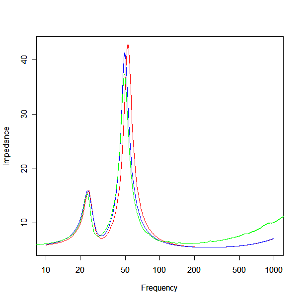
The red plot shows the theoretical driver impedance and the green plot the measured impedance. The lower resonance peak pretty much coincides but the upper one is a little lower than theoretical. Plotting a second theoretical curve but with the resonant frequency of the driver shifted from 42Hz to 39Hz produces the blue plot which is almost identical to the measured, apart from the deviation at high frequency, which shows a considerably larger leakage inductance than claimed in the manufacturers specs. From this I’m guessing the deviation is basically due to the free air resonance of the driver being slightly lower than the manufacturers specs but well within reported tolerance.
The other thing to note is that the height of the impedance peaks between the theoretical and measured are almost the same meaning the actual box Q is about the same as the design figure. However, the blue plot has the box Q parameter set to 6 whereas the red plot has it set to 7 meaning the actual box Q looks closer to 6 than 7. This is interesting because the box isn’t lined with acoustic insulation. All it had in it at the time of measurement was about a 30cm deep layer of polyester pillow stuffing loosely packed down the bottom of the enclosure and the remainder is completely untreated. It should then be obvious that completely lining the box is probably a bad idea as it will lead to a lower box Q than we desire.
Having listened to a completed prototype I can say that having this level of stuffing does not present a problem in terms of box colouration. Without consciously considering it, this is unlikely to be an issue in this design because the standing wave and panel resonance frequencies are outside of the operating range of the driver which is cut at 150Hz. As such, I haven’t bothered treated the box with bracing for stiffening or viscous material lining the insider walls (such as bitumen) without audible detriment. If the woofer were crossed at 400Hz instead it would undoubtedly be a different matter.