The information below gathered from the web may help give a better understanding of electret mics
Electret microphones are a variant of condenser microphones that mostly utilize a permanently charged diaphragm over a conductive metal back-plate. Electret mics are also capacitive sources requiring very high impedance loads but are invariably provided with in-built FET impedance converters. Their output impedance is typically in the range of 500 to 5000 Ohms and they like to be loaded with at least their own impedance. Widely used electret microphone capsules tend to be small, even minuscule, cheap and light. Back-electrets microphones use a charged back-plate instead of a charged diaphragm. These may or may not be phantom powered. Electret and back-electret microphones have special preference for voice communication, where clarity of speech is essential at the sacrifice of perfect sound reproduction. For low cost applications, electrets offer the highest sound quality and have quite a high output, easing the need for a high quality preamp. They can be obtained in omni directional or directional models for different applications. You can find electret microphone inside many modern electronics devices that have built-in microphone (video cameras, telephones, cellular phones, voice recorders, computer microphones). In professional audio work electret capsules are used in some (semi) professional microphones and in small lavaliere microphones (those which clip to the clothes are are taped to the skin of an actor in theatre). Electret microphones are also used in many audio measurement applications, because there exist electret microphones that have very good response (both frequency and impulse response). Ceramic and crystal mics are high impedance and appear to be capacitive sources. Some of the signal level is lost due to the shunt capacitance of the cable. The input impedance of the equipment needs to be at least 1Megohmto avoid loss of bass.
Earle
Simulating a car environment
-
Erik Nygaard
- Posts: 1
- Joined: Sun May 30, 2004 10:11 am
Re: You are correct
Har/Bal wrote:Mike
Thanks for the correction and yes you can actually tune your room using this method.
Earle
A couple of questions:
Since the direct sound from your speakers will hit the mic first
and then the sound reflections from the room,
wouldn't you be making a corrective filter for your speakers rather than the room?
Or do you point the mic away from the speakers using a cardiod or other pattern?
Re: You are correct
Erik Nygaard wrote:Har/Bal wrote:Mike
Thanks for the correction and yes you can actually tune your room using this method.
Earle
A couple of questions:
Since the direct sound from your speakers will hit the mic first
and then the sound reflections from the room,
wouldn't you be making a corrective filter for your speakers rather than the room?
Or do you point the mic away from the speakers using a cardiod or other pattern?
Erik,
If you place the Mic at your normal listening position and direct the mic at the speaker then you will be measuring the pink noise response of the speaker plus room as you would hear it (or at least an approximation thereof).
The Mic will pick up both direct and reflected sound as you would do if you were sitting there and this is easily demonstratable using a 2 channel FFT spectrum analyzer to measure the transfer function from loudspeaker input to microphone output. If you do you'll find that the response is very lumpy owing to the constructive and destructive interference from direct and reflected sounds being superimposed on one another.
That is why loudspeaker frequency response measurements are generally done in free field or an anechoic chamber (for those who can afford one). It is true that you can truncate the measured impulse response to obtain a frequency response closer to what happens in free field but it invariably suffers from limited resolution as a result of the truncation operation.
By the way, a cardioid pattern is a reasonable pattern to use in my view, given that each ear has a directivity pattern that is largerly directed to one side of the head only and slightely forward. If you position the mic in the correct orientation you'll end up with a measurement that is representative of one ears response. Hopefully you'll find that left and right are near enough the same, otherwise you may have some real problems with your speakers and or listening environment.
Regards,
Paavo.
Regards,
Paavo.
-
mflorio
it worked !
Paavo & Earle,
I got my little Behringer mic today and tried the experiment using Earle's pink noise mp3. The results were nothing less than stunning ! I was able to correct for quite a few problems. I dug up the frequency response graph for my speakers just to check it against the recorded pink noise too. In my HB filter, I pretty much matched the pink noise ref, but kept the gentle LF roll-off designed into the speaker itself.
Strange thing I noticed in the pink noise mp3 (which I converted to wav in order to analyze it with HB) is that HB showed a spike at 14khz, right before the steep HF roll-off. Maybe this is a function of the mp3 encoding ? My room recording showed the same spike. I ignored the spike in my filter, and kept it flat.
Anyway - Paavo, it would be GREAT to have an option in Har-Bal to apply a calibration filter (as you stated in a previous post). The filter should *not* affect the traces on the graph, and should *not* be applied when recording the output file to disk. It should be for monitoring only. This would be a fantastic feature.
I tried this on my mid-field 3-way speakers, by the way. I'm going to do the near-fields tonight. Hopefully they will fare better (according to the philosophy of near-field monitoring, they should...).
Thanks again for this great tool and all your advice and help !
Mike
Re: it worked !
mflorio wrote:Paavo & Earle,
I got my little Behringer mic today and tried the experiment using Earle's pink noise mp3. The results were nothing less than stunning ! ...
Strange thing I noticed in the pink noise mp3 (which I converted to wav in order to analyze it with HB) is that HB showed a spike at 14khz, right before the steep HF roll-off. Maybe this is a function of the mp3 encoding ? My room recording showed the same spike. I ignored the spike in my filter, and kept it flat.
Anyway - Paavo, it would be GREAT to have an option in Har-Bal to apply a calibration filter (as you stated in a previous post). The filter should *not* affect the traces on the graph, and should *not* be applied when recording the output file to disk. It should be for monitoring only. This would be a fantastic feature.
...
Mike
Mike,
Thanks for the feeback. I've know about that mic for a couple of years now and have intended buying one but just haven't got around to it. You've convinced me that I should!
The peak in the response @ 14kHz is, I think, as you suggest a feature of mp3 encoding. I've seen it before in tracks (that I had the original cda format for) that I shared with Earle a month or two ago when we were evaluating the effect of some third party software. As you say, you should either ignore it or then burn the recorded sound direct to wav or cda and analyze that instead.
All your feature suggestions are exactly what I intend doing. As it looks like such as simple yet powerful addition I'll most likely put it in sooner or later. It is one of those things that just get me excited thinking about what it might sound like to be able to reasonably accurately compensate for room effects while doing Harbalizing!
Thanks again for letting us now how you got on. I'm really excited about getting one of those mics now!
Paavo.
-
mflorio
Paavo,
If you ever get around to making a plugin version of HB, this would be a great reason for it. In other words, you can use the calibration filter designed in HB as a static/read-only EQ that can be placed at the end of the stereo bus in any audio application (that supports plugins).
By the way, I also acheived good results on my near-field testing too.
Mike
The problem with most studio mikes is they are not designed to have a flat frequency response so you'll need to compesate for this when you make an adjustment.
If you are really serious about measuring your listening environment performance then I'd recommend buying a measurement microphone. As I mentioned earlier Behringer makes an inexpensive measurment mic (ECM8000) which has an onmi-directional pattern and also has a low LF corner frequency. Here is a link to the product description if you are interested.
http://www.behringer.com/ECM8000/index.cfm?lang=ENG
Regards,
I just Purchased one of these mic's on E-bay for 46 Bucks in new condition.
"Who's worried about the marsh when your up to your waist in Alligators"
-
Guest
I just picked up an ECM8000 at Guitar Center in Rockville, MD for $40.
I, too, am amazed at just how uneven my room response is. I am using KRK V8II's which are spec'd to be +/-1.5dB from 48Hz - 20kHz. Measureing the pink noise response of the speakers and room, I am getting a few peaks and dips that are as much as +/- 10dB! It makes me realize more than ever that I really need to treat my room.
This does bring up a question, though, about how much "Har-balizing" can be done without significant negative consequences. I created a room correction filter that converts my room response to nearly an exact match of the pink noise input file. When I apply this filter to a song file (my own work, and several professional releases), I find that the sound quality suffers. It almost seems as if there is some phase problems, but I can't say for sure. All I know is that it sounds worse than without the filter.
The filter I created is pretty drastic - far more so than any filter I would ever create to adjust an actual song. Again, there are several EQ points that are +/-10dB, and there are probably 30 different EQ points altogether. So, this makes me wonder if making drastic changes like this is more than even Harbal can handle effectively.
Tom Boughner
-
mflorio
My filter was pretty drastic in some spots too (I'm using JBL 4410's). Escpecially around 125Hz, where I had a huge dip. However, 90% of the commercial recordings that I tested my calibration filter on actually sounded much better. I didn't test my own stuff because I would have already compensated for my room problems in the initial recordings, and applying a calibration filter after the fact would definitely screw things up. Maybe the 'professional releases' you're listening to were not mastered well. How do the traces in Har-Bal look ?
-
mflorio
Just one more thought...
Don't touch anything below 48hz in your filter. In other words, the pink noise reference will be flat, but your speakers will have a natural roll-off that is intrinsic to the speaker design. Keep the slope in your filter. Same on the high end. In fact, I didn't touch anything over 14khz in my filter.
Mike
Tom & Mike,
A few points to note with regard to room equalization / treatment.
Firstly, when measuring the response make sure you are doing it one speaker at a time with the other one silent, otherwise you'll have a huge interference pattern that will likely make the response look worse than it is (note the interference isn't a big issue when you've got your head sitting at the listening position cos it blocks the HF sound from interfering).
The 125 Hz dip you speak of you should probably not correct for. Most likely this is the floor or ceiling reflected wave destructively interfering with the direct sound. If you correct for it you may have more bass but my experience is that it does not sound as good, I guess because your brain is expecting the effect of a floor reflection and you are trying to eliminate it.
As Mike pointed out, don't try overly extended the LF response of your setup. Keep the natural roll off otherwise you'll overwork the drivers and they probably won't handle it well in any case.
Finally, be aware that a good mastering studio will not necessarily have a flat pink noise response. In fact, I'd argue that it most likely would not, especially if you are monitoring in the mid/far field. Conventional wisdom on acoustics says that rooms for music performance and reproduction should have a largely flat reverb time from around 400Hz upwards and below that progressively longer reverb times. This adds warmth to the sound. As a consequence the pink noise response of ideal drivers in this room in the mid/far field will have a corresponding boost in the LF end of the response.
Another good reason for this reverb time characteristic is that most living rooms in most houses are carperted which naturally gives a reverb time characteristic along these lines (although they suffer from the problem that most damping is on the floor and not spread evenly throughout the room) so this response is more representative of what the average listening environment will be.
My opinion is that you should only use EQ to correct for loudspeaker frequency response problems and not reverb time problems. EQ cannot effectively correct for a poor reverb time characteristic and if you do it will sound odd because the sound you hear doesn't tally with the acoustic environment.
If you are serious about this then perhaps you should do some reverb time measurements to see how your room behaves. The typical approach is measuring the sound from a balloon that you burst with a pin and see how long it decays away. If you've got an application that can display the impulse in a spectrogram view (ie. spectrum versus time) then you can see how the reverb time behaves across the band. I used Adobe Audition (formerly Cool Edit) for this quite effectively. By the way, the reverb time is define as the time it takes for the sound pressure to decay to -60dB from the peak value.
Regards,
Paavo.
-
Har/Bal
Motown CD
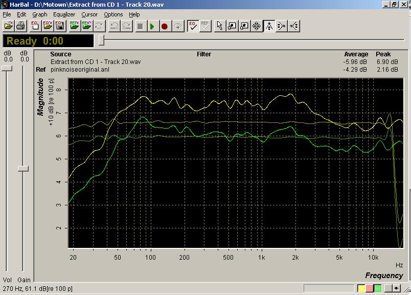
Interesting discussion....I recently got a hold of an old Motown cd and was amazed at the fidelity. These songs were recorded in the mid 60's
The sound is amazing so just for the heck of it I extracted the songs and loaded them into Har-Bal so I could study them.
I opened a pinknoise.anl file as a reference just to see how balanced they were and it confirmed what I had been thinking all along. All of the songs were very close in terms of shape. Almost horizontal (close to even with the exception of subtle dynamics.
Once the song is balanced you can then proceed and sweeten to taste.
The biggest problem it seems that a lot of folks have is initially balancing a song as a first step in equalization.
Take a look at the screenshot. Most of the songs were similar. in shape.
Look at how it lines up with a snippet of pink noise (green line).
www.hdqtrz.com/Files/motown.jpg
Earle
-
Har/Bal
Good article
Below is a link explaining the frequencies and their relationship to each other which I found to be quite informative.
http://www.dak.com/reviews/Tutorial_frequencies.cfm
Earle
http://www.dak.com/reviews/Tutorial_frequencies.cfm
Earle
-
zumbido
Paavo, a pink noise source?
Paavo,
You made available an .mp3 file of pink noise.
Anyway you can make a .wav or .aif file available?
I just picked up a Behringer ECM-8000, on your recommendation, and am getting ready to analyze my mixing/mastering room.
thanks,
zumbido
You made available an .mp3 file of pink noise.
Anyway you can make a .wav or .aif file available?
I just picked up a Behringer ECM-8000, on your recommendation, and am getting ready to analyze my mixing/mastering room.
thanks,
zumbido
-
Har/Bal
Pink Noise wave file
Zumbido
We just placed a pink noise wave file at the same address for you.
www.hdqtrz.com/Pink
Earle
We just placed a pink noise wave file at the same address for you.
www.hdqtrz.com/Pink
Earle