Summer Project – Bass Guitar Cabinet (and Amp Eventually)
I’m very much in summer holiday mode at the moment and simply aren’t in the mood to do coding development, despite the myriad of ideas running around in my head pertinent to that end. To stay fresh with enthusiasm I need suitable distractions to keep me feeling alive and not tired with the mundanity of it all.
One of my casual persuits at my day job and main source of income is playing percussion in a band that meet approximately once a week to jam for about and hour around lunch time. Two of my band members, one bass player and the other a guitarist (and sometimes bass player) have the same combined cabinet / amp (one each) they play through and whilst it is ok, I’ve always thought the bass guitar sound emanating from it was less than satisfying. It certainly never sounds like it is producing anywhere near the low bass of my monitors at home and at a guess, probably begins rolling off at around 70Hz or so. Given the 10 inch driver in a sealed cabinet of maybe 40 litres or so it would make sense that that would be the case. That just got me thinking as to how hard could it be to make something of a similar size that gives a way more satisfying bass performance than that. So now I have a new project…
How hard could it be?
How hard could it be to make something better at an affordable cost or at least a cost similar to what they paid? Given my experience in making my own monitors, it would certainly be considerably less taxing than that as any idiosyncracies of driver frequency response (provided within a reasonable range) can be just absorbed into what might be defined as the “character” of the amp/cabinet. In making monitors that need to reproduce all instruments that freedom is simply not available but in this case all I need to concern myself with is how the cabinet design will work to produce adequate bass. It is only important to check that the reported response of the chosen driver looks uniform enough to not present major issues but it need not be flat and indeed, it may be better to not be flat if the colouration it provides works in favour of a better sound from the bass guitar.
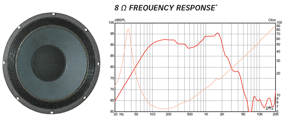
So I set about looking through what drivers I could find for bass guitars at Parts Express and pretty soon came across something that looked like a perfect fit for my needs. That driver is the Eminence BP 102. The driver has characteristics well suited to a vented (bass reflex) enclosure that would be capable of producing extended bass with relatively small box volumes and the driver response in other parts of the spectrum look suitably well controlled. It shows a degree of boost around 1-2kHz and some weakness around 500Hz which could be relatively easily overcome with guitar amp tone controls / EQ.
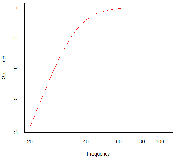
Doing some swift modelling evaluations it became apparent that with this driver in a vented cabinet of 74 litres (2.61 cubic feet) and a box frequency of 35Hz would give a -3dB point of around 37Hz, be -6dB at around 31Hz and -12dB at 25Hz. Not at all bad on a cubic box measuring 42cm (16.5 inches) inside length (ie. 42 by 42 by 42). That should be small enough to carry with one hand (given a strap) and enough bass to make a real impression, and for those wanting to play loud, the voice coil rating (200 Watts) should make levels in excess of 100 dB SPL. It remains to be seen if the vented enclosure with that level of extension and high SPL will lead to significant cone breakup from over-excursion, although in the purpose I have for it that is highly unlikely as we won’t be playing that loud.
In answer to my question I think the conclusion is a clear “not very hard at all”. Unless there is something truly amiss with my modelling then this looks very possible. As it is the same modelling code that I used to design my monitors (and they work as designed) I have no reason to doubt it. It also worked fine for my second pair of smaller hi-fi speakers I designed for the holiday house so the only possibility of it being wrong would lie with the published driver parameters being incorrect. Not very likely in my view so I’m keen to try this out.
A more detailed look at the cabinet design
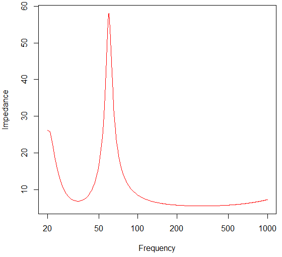
As mentioned before, the settled on design parameters were a box volume of 74 litres and a box frequency of 35Hz. To make the cabinet as physically small as possible the best geometry is cubic because it is the greatest volume for the smallest surface area, so therefore is the most compact. Probably not ideal in terms of resonance modes within the cabinet but this isn’t a Hi-Fi application. Going on my calculation the first mode should be around 410Hz which could well help to fill in that mid range hole in the driver response so I’m happy to run with it. I may make the dimensions slightly different to broaden the resonance but I think a basically cubic design is the way to go.
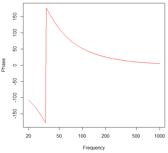
The Frequency Response, Phase Response and Impedance according to the design are as follows
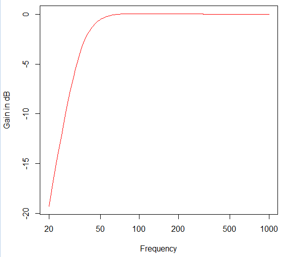
The frequency response is nominally flat with no obvious peaking. Roll off is smooth and controlled as well. The following provides a closer look at the detail which again confirms the bass extension the cabinet provides.
Remember that these responses represent the free field case but the cabinet will likely be sitting on the floor. That means that instead of radiating into a free field it will be radiating into a half space, or if you are close to a wall, a quarter space. That proximity to the floor and walls will undoubtedly lift the bass output quite a bit so in real circumstances it is more than possible that it will be producing usable output below 30Hz. As an example I can look to my own monitors which have a theoretical -3dB cutoff of 27Hz but measured in my room it is essentially flat down to 20Hz. Also, those monitors have high standing drivers (around 45cm above the floor) and vent so the floor coupling would be less than for this bass guitar cabinet. It should be interesting to see how much lift is obtained in the physical realisation of this design.
The components I’m looking at
Here is a run down of the components I’m looking at getting to implement this design, some essential, some niceties.
- BP102 Driver – https://www.parts-express.com/eminence-legend-bp102-10-bass-guitar-driver-200w-8-ohm–290-471
- Peavey Grill – https://www.parts-express.com/peavey-10-metal-speaker-grill-kit–248-8798
- 100Watt Mono Amp – https://www.parts-express.com/wondom-aa-ab31184-100w-mono-amp-board–320-3341
- Precision Port – https://www.parts-express.com/precision-port-4-flared-speaker-cabinet-port-tube-kit–268-352
- Metal Corners – https://www.parts-express.com/penn-elcom-c1824k-metal-cabinet-corner-black-2-leg–262-155
- Speakon Socket – https://www.parts-express.com/amphenol-sp-2-md-speaker-connector-2-pole-d-flange-panel-mount-black–092-0160
- Speakon Plug – https://www.parts-express.com/neutrik-nl2fx-speakon-connector-2-pole-cable-mount–092-198
Luckily I don’t need a power supply for the power amp module as work was chucking away old 150 Watt Dell computer power packs that will re-purpose nicely. I will need a rail inverter to make a split supply for the pre-amp section but that is another part of the project. In fact, I plan to make the amp module completely separate from the cabinet so that isn’t an issue at the moment. I can build and test the cabinet without a pre-amp, and still have work to do on that part of the project anyway. Going by my calculations, the hardware less the timber to build the cabinet amounts to $120 US (excluding the power amp module). That seems pretty affordable to my mind. The power amp module amounts to $30 US and I guess I could make a decent pre-amp for an extra $50-$70 US so a complete system might be in the order of $220 US less the cost of cabinet construction. That all seems pretty affordable and I’m really curious to try…