Loudspeaker System Design – Polar Response and Phasing Issues
Recall from previous discussions that it is my firm belief that the strength of a loudspeaker system lies in uniformity of the polar response. For that reason it is important to consider the polar response of the system in the vertical plane, not just the horizontal plane, which we can infer with some accuracy from the manufacturers data. Not only that, the performance of the mid-range tweeter crossover will be influenced by the phase relationship between those drivers, a parameter not found in manufacturers data. For that reason, to be able to come up with a satisfactory crossover for those drivers, we must first measure the driver responses.
Measuring the Driver Responses
To measure driver responses we need access to a spectrum analyser. In a previous life I wrote a software based one call AtSpec, which has now fallen by the way side, but which suits my needs fine for this job. I have some desire to turn it into an open source project though the code needs major re-working to make it portable so that will just have to wait for a future opportunity.
What is required in this case is to measure the frequency response of the tweeter and mid-range drivers at various angles offset from on axis. Most importantly, the measurements must be phase consistent across drivers. By that I mean that a substantial part of the phase response is from the pure time delay of the sound traveling from the driver to the microphone and that time delay is determined by the distance between the driver and the microphone. If that distance distance is not exactly the same for the tweeter and mid-range measurements then we will introduce a phase error due to measurement accuracy. For that reason it is important to find a way of conducting the measurement in such as way as to minimise this source of error.
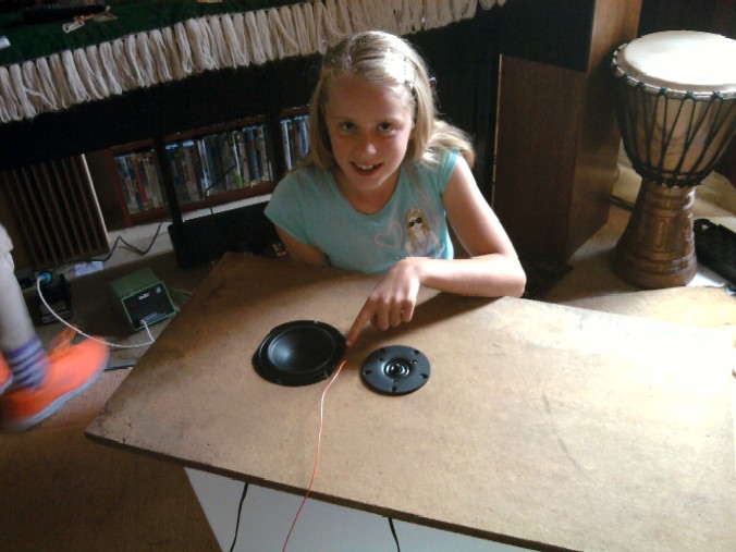
The approach I took was to mount the tweeter and mid-range on the same baffle at the same time and use a string bound to the baffle as a reference measure of the distance at which to measure the response. Then at each angle of offset, measure both the tweeter and mid-range responses without changing the microphone position. This then ensures a consistent microphone distance. The one down side is that the microphone is never truly on axis in the non-measured plane (like it should be) but at a shallow offset of may 2-3 degrees. This is a small penalty to pay for phase consistency and will have little effect on being able to design a good crossover, which is the whole point of the exercise.
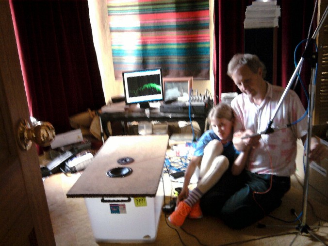
To illustrate see the photos below. Apologies for the blur. My eldest daughter failed to hold the mobile phone still while taking the photo. Anna-Kaisa is pointing out the string (or wire in this case) used to gauge the distance between the microphone and the mid point between drivers. Kaolhinn is helping me (is she?) demonstrate using the wire as a gauge, though you’ll struggle to see it because of the photo blur. The drivers are simply sitting on top of a baffle made out of a piece of particle board flooring off-cut which in turn is sitting on top of a plastic box. Pretty crude but perfectly acceptable for find the answer to my question.
In my case I measured the responses at a distance of around 70cm at 10 degree intervals from 0 through to 90 degrees. Because the measurements are in a room rather than an anechoic chamber, the responses are coloured by room reflections. To improve the usefulness of the results for the purpose in question, I took the impulse response measurements and windowed them, thereby cutting off a large proportion of the room reflection components. This makes the results easier to read at the expense of reduced low frequency resolution, though the low frequency end is coloured by my small room and remember the point of the exercise is to merely figure out out how the responses will add at the crossover point, which is clearly not at a low frequency.
Modelling the Possible Crossover Response
Again, I used R and some R-Scripts to model the polar response behaviour of the drivers. This involved reading in the impulse responses from AtSpec output, windowing them, transforming them into the frequency domain and then summing them through a theoretical crossover response. The crossover response used was a third order Butterworth response which theoretically gives a flat response when subtracting the low pass and high pass filter outputs (adding results in a deep notch because of the phase relationship between the high and low pass filter outputs).
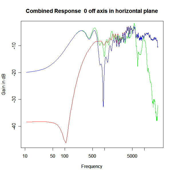
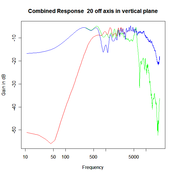
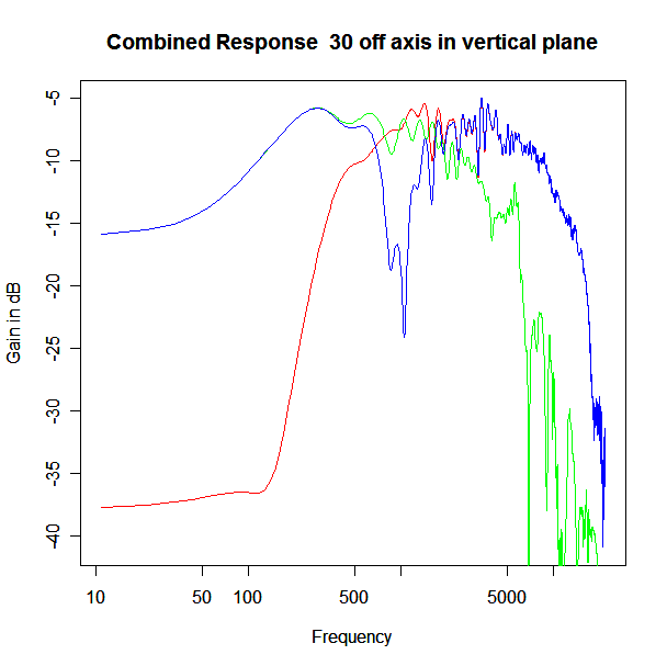
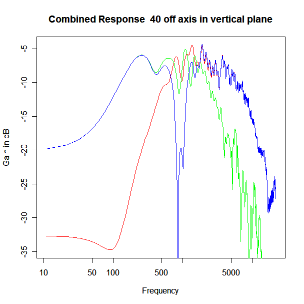
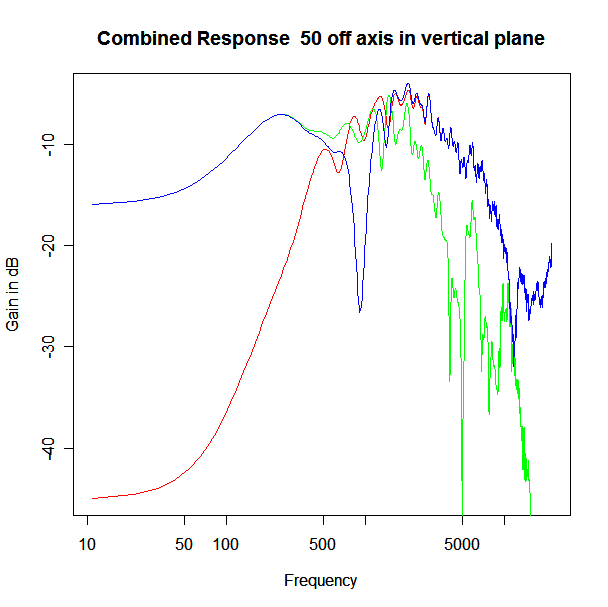
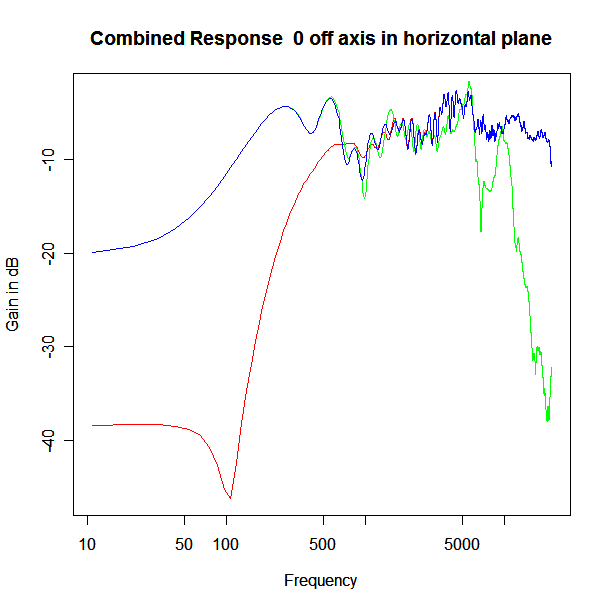
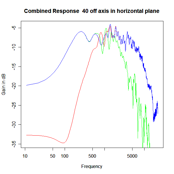
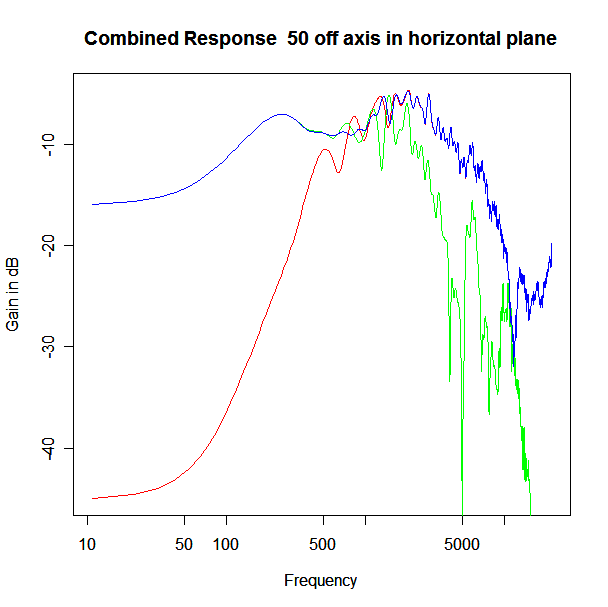
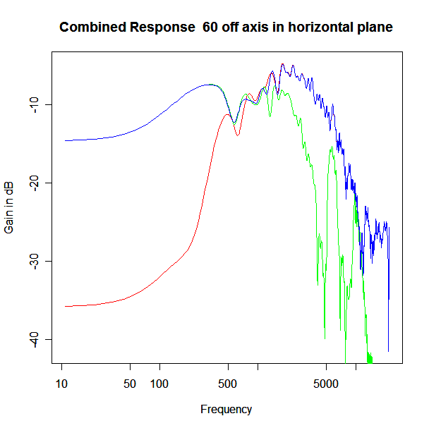
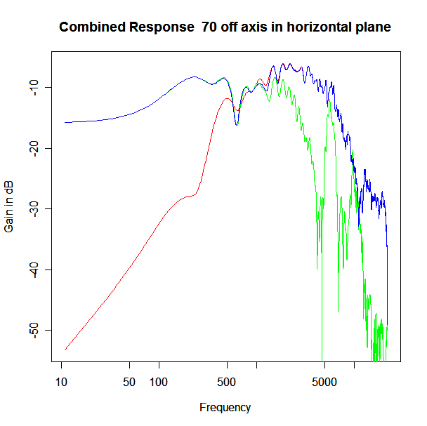
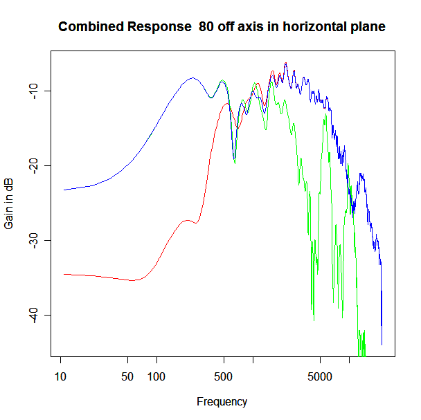
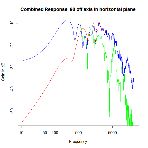
Applying this crossover form with a crossover frequency of 1kHz we obtain the response above. The red plot is the tweeter output, the green plot is the mid-range output and the blue plot is the combined output. Note the big notch! This occurs because of the phase relationship between the tweeter and mid-range outputs, which is not simply flat. It is shown below.
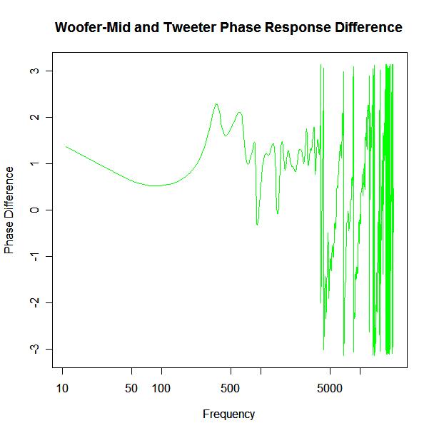
It is anything but in-phase. At the high frequency end there is a lot of phase reversal which stems from a pure time delay factor between the mid-range and tweeter, the mid-range output coming after the tweeter output. A secondary factor is a phase reversal of the tweeter response as frequency passes through resonance (the tweeter resonance is around 450Hz which is close to the crossover frequency).
To obtain a good crossover behaviour we must first account for this phase discrepancy by physically setting back the tweeter to remove the pure time delay term, then adding a phase compensation in the form of an all-pass filter to remove the influence of the tweeter resonance on the phase relationship between the drivers. Doing so we obtain the compensated phase difference shown below.
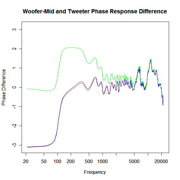
Here the green plot shows the phase difference just with time delay compensation (tweeter set-back), the red plot shows the phase difference with inclusion of an all pass response on the mid-range filter and the blue shows the theoretical all pass response determined by the lumped parameter model responses of the drivers. The later one I find interesting because it suggests that in this case at least, the theoretical response gives a good indication of the real response even though it is extending into the non-piston range. I certainly wasn’t expecting that to be the case. I don’t know if this is generally true or just true for this driver but it is an interesting observation all the same. The tweeter set-back is 24.5mm. Quite a substantial distance and perhaps more than you might expect from visual inspection of the drivers.
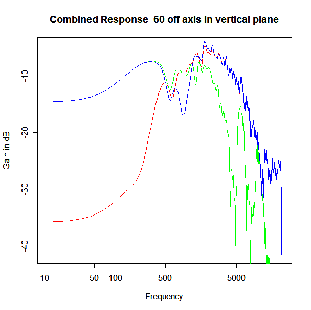
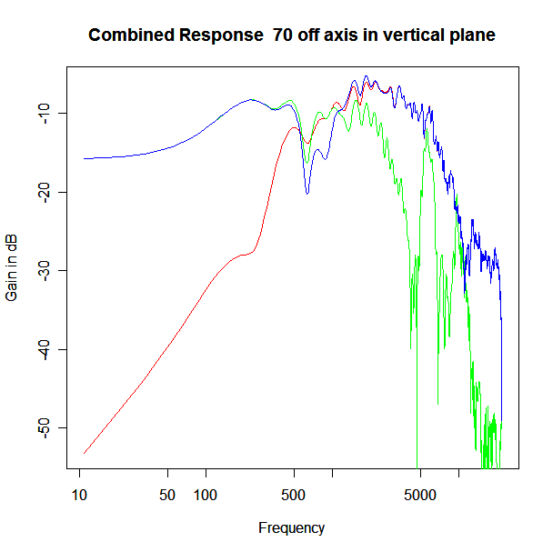
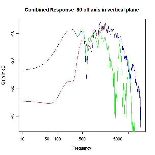
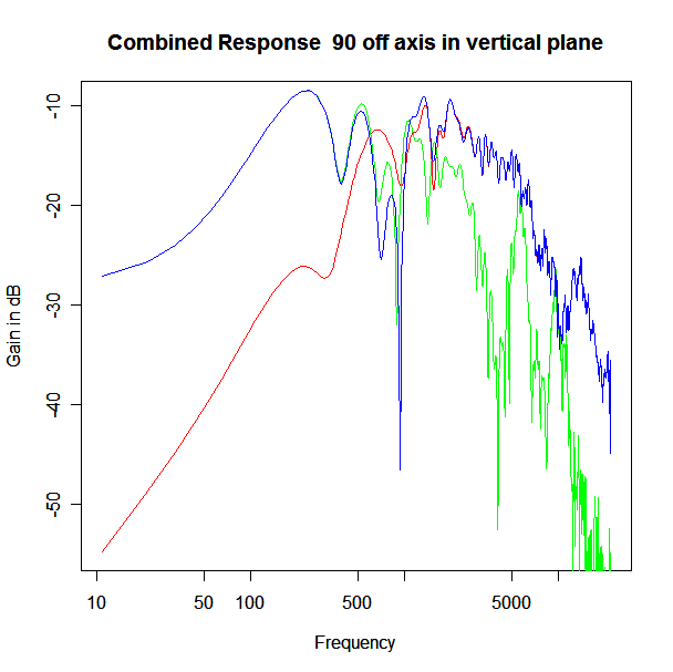
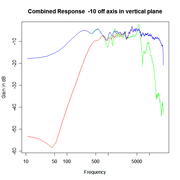
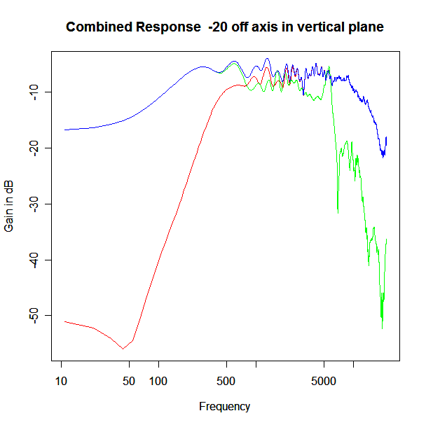
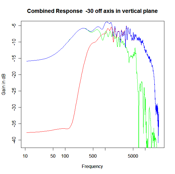
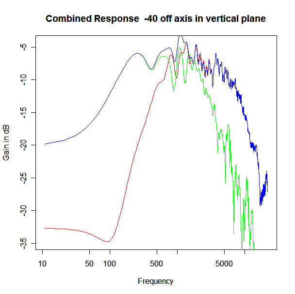
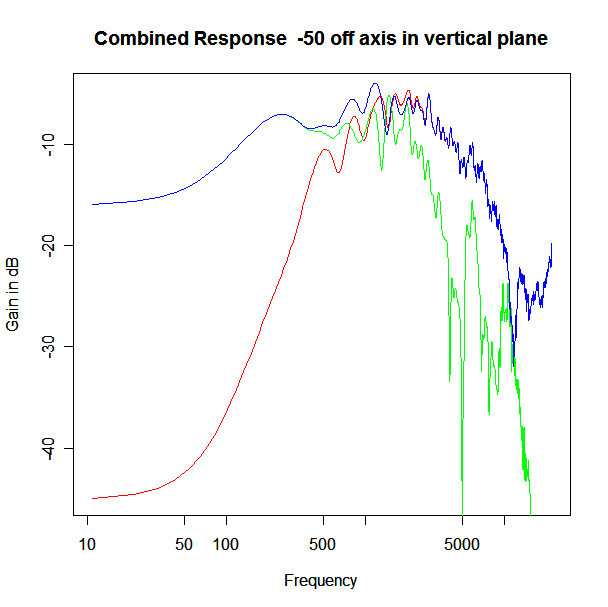
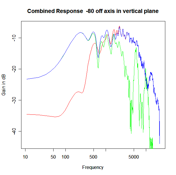
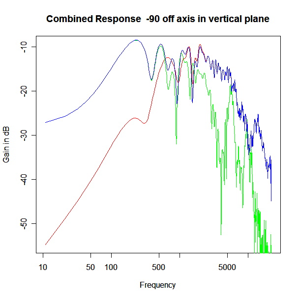
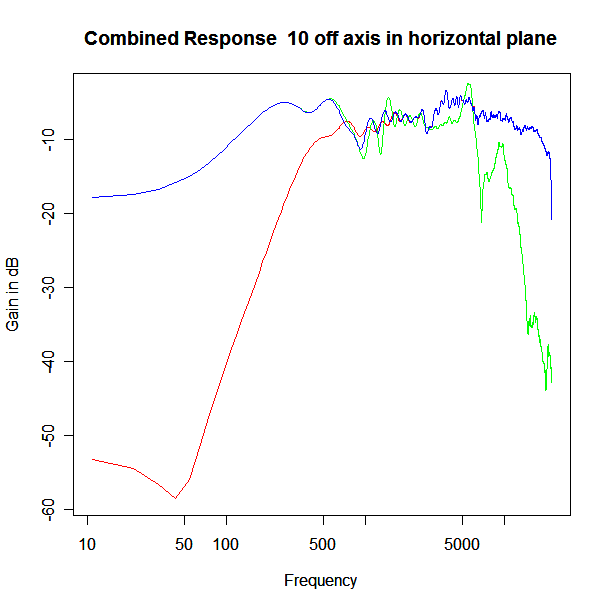
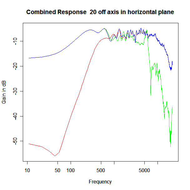
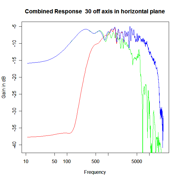
Adding the phase compensation to the drivers and then applying the 3rd or Butterworth prototypes we obtain the following responses. The Horizontal plane responses are all well behaved with the drivers combining as expected. The interesting results are the vertical plane ones which show a remarkably uniform response for negative angles and some notching for positive angles with notch bandwidth of typically an octave or less. The sign of the vertical plane angles are taken in a normal sense of having the tweeter mounted above the mid-range and angles above the tweeter regarded as positive. Noting that, it should be clear that in this configuration the best response is radiated to the floor, which given most living rooms having carpet, is not at all sensible. It would make far more sense for the best vertical plane radiation to be directed upward instead, which suggests that the best driver configuration for this crossover is to have the mid-range unit mounted above the tweeter! It isn’t commonly seen in commercial loudspeaker systems though I’ve certainly seen it done with Mission speakers in the past, so maybe there was a scientific explanation to the apparent madness!
It should be noted that this isn’t the only possible approach to designing the crossover. It is also possible to simply stipulate a 3rd order crossover, compensate for the time delay, omit the phase equaliser and optimise for a flat crossover response. I did try this and although it worked for the on axis case, the off axis performance was inferior to the response obtained using this approach and by quite a large extent. Adding phase compensation adds crossover complexity but it makes a major impact on the quality of the off axis crossover behaviour so it appears to be well worth the added cost.
That pretty much wraps up this installment of the crossover design saga. Next to come is designing the entire crossover, modelling the theoretical behaviour with exact components, with actual component values and with the complete NGSPICE circuit simulation taking into account impedance mismatch effects. I’d point out that my previous discussion of the woofer-mid crossover point had a mistake in that it omitted the effect of the phase equaliser needed for the mid-range driver to cross well with the tweeter. As such, it is re-done using a “whole crossover optimisation” approach in my next installment.
Horizontal Plane Polar Response
Vertical Plane Polar Response